The Marlin firmware, for my Prusa I3 clone 3D-printer, has been a learning curve, for me, with programing a large project with arduino.
I have put forth suggestions for fixes and new features like: DHT sensor support, case light. The case light was taken care of rather quickly, but the DHT sensor was left to me.
The digital temp and humidity (DHT) sensor was quite the pain to incorporate due to not really knowing the layout and formatting of the Marlin firmware. I set out to get more familiar with it to get it working and I finally did.
Next up, was to learn GitHub on how to submit new or changed code to the Marlin repository.
Learning git was definately a challange. I made several mistakes when submitting code, and screwed up my repo several times. Not a bit deal, because the one thing I had down pat was how to make a copy of the Marlin repo. So, I could easily start over as many times as I needed to.
So, I finally got the DHT code working and sumitted to the Marlin people. It is now up to them if they want include it in the firmware for everyone. But, now that it's on the repo, anyone can give it a try before "merging" it into the main stream.
On that note, I noticed a submittal for adding RGB strip support. I got that mod and started testing it. I found that it didn't fully work as intended. So, I started tweaking and fixing. I got it to work flawlessly and submitted my changes to the original submitter of this code. I waited over two weeks and no responces. So, I created a new sumittal to Marlin, referencing the original work.
A month or so passes and someone asked for RGBW support. I changed up some of the code to do so ans sumitted the changes.
A week now goes by and someone else asked for addressable RGB strip support. Well, this took a little more work and was more worried that it would mess with Marlin's main operations due to timing issues. I was later directed to a fastled arduino library that made it work without too much of an issue. I then submitted those changes.
The Marlin team took a look at the RGB strip code after some debate and wanted some changes done for complience and uniformity. These would just about require a full re-write of the RGB strip code. But, I did get it to the standards they wanted. They have stated that it would not likely be merged until the next release (1.2.0).
Well, I then started on on some other parts, like making a menu system for the united bed leveling system (UBL), and a menu system for RGB light control.
Both of these require a computer with a connection to the printer so the user can send manuall commands to operate these new features. I am trying to give the option to use these features using an LCD on the printer.
I have these done now and have submitted the changes to Marlin.
Other additions I've done is, display the type of leveling scheme in use and show "Generic" when power supply =0, on the "About Printer" screen in the LCD menu.
Other than making and submitting code changes, there have been numberous people with issues thay I've tried to help. Some people give snotty replies, others give big praises. (That goes for every support position on this planet.)
Again, this is getting fun for me. I am learning a whole lot more than just playing with lights on an arduino.
Sunday, April 30, 2017
Marlin Firmware
Thursday, June 30, 2016
Arduino RGB Clock
I was thinking about making an LED clock with an arduino. So, I was wondering what would make my clock stand out from the rest of the arduino LED clocks projects that are already out there.
I was remembering an RGB cube I built. I then said that I would set out to make this an RGB clock.
First, I setup a 4-digit seven segment display and got the clock code working. Then I was wondering if I could get a temp/humidty module to work with this also. I started with setting this up and ran into hurdle after hurdle.
I stumbled upon some code that was very simular to what I wanted. This code display the temp, then the humidity, then the time. Well, that code didn't really work, but I did some tweaking and tuning and got it to work.
Now that I had a working clock with temp and humidity, it was time to make a display to the size I was imagining.
I found a 3x5 dot matrix frame to hold 5mm LEDs in a clock digit arraingment. This was perfect. I whipped up this frame on the 3D printer and started stuffing it with the commom cathode RGB LEDs. I then soldered all of the cathodes for each digit separately.
Then I was on the tedious part of soldering all of the leads of the first digit to the second digit, then from the second digit to the third digit, then from the third digit to the forth digit. Then the two colons. I tested each section as it was going together. When I got done, all was good.
Now it was time to solder a wire to each lead from the red, green, and blue on each LED on the first digit. Because of the fifty wires needed, I chose to use a ribbon cable so I could have one ribbon for each color. This made things easier by not having to number the wires. I just labled the ribbons by color: Red, Blue, Green. I got all the wires in place and soldered some connectors to the other end.
Now that the rgb display is assembled and wired, now it was on to get the code to work. This was going to be a little challenge because of the rgb that can give me seven colors (without pwm control).
Well, the code did prove to be a challenge that took me a while get it sorted. But, it worked just fine.
I wanted to add some shift registers to reduce the number of arduino I/O pins needed so, that forced me to make a circuit board to do that. That is in another blog.
After getting the rgb pcb display boards, I started designing a box to house all of the compnents of the clock. That took a few attempts and got it done, put it all together and I now have the project finished close to what I had envisioned.
The next option is to add buttons to adjust the time.
This was fun and time consuming.
Monday, May 30, 2016
3D Printing
I have been interested in 3D printers since they were first announced. I couldn't afford the 5g's they wanted for them. When they came down to a grand, I still couldn't justify that amount of money for something that might be a flop.
I was getting into the Arduino stuff (to try and stay a step ahead of the g-kids) and ran across a board for the Arduino called Ramps. I had to look more into this and what it was used for.
I found that the Ramps board was developed for running a 3D printer. I got really interested in this because it was open source and all of the parts needed to build the printer can be gotten at various places locally or online for cheap.
I got a little worried that I was not going to select the correct parts for everything to play nice together. So, I opted to purchase a kit from FolgerTech called the Prusa i3. I liked this model because of the openess of the print bed and the ease of repair.
When I got the kit in, I got busy putting it together. the printer went together fairly easy. Instructions and all related software are provided via a Google Drive link.
The instruction also walked me through all of the required settings to get the printer printing. I found later that these settings are rough and slowly got some things ironed out.
I got to printing multiple things, but had a hard time getting every part to stick to the print bed reliably. Online searches reveal a mixed concensus. I did find that blue masking tape worked nice for PLA plastic. I have now found that the green Frog Tape (found in Wal-Mart) is also working really well with PLA and longer life. ABS is much more sketchy on this.
After finding material that would keep the parts attached, now it was time to consentrate on actual printing.
Most designs printed just fine, but larger prints seems to cause the filament to skip and miss sections of the print.
I later found the skipping issue to be the retract distance was too much. This retraction of the filament is used to prevent the plastic from creating webs and such when moving from point to another without intending to lay down any plastic. when this retraction is too high, it cause the molten plastic to be pulled up into past the heat break. This now cools. And when enough plastic builds up into the colder area, it can be too much to push the filament through. That is when you hear the 'clicking' noise.
I have now printed many different parts in PLA and at varying sizes and complexities with no issues.
Thursday, April 7, 2016
Circuit Boards
Well, I have always tinkered with the idea of making my own printed circuit board. I read and researched everything from power layouts to interference avoidance. Even looking for tips and tricks.
I made my first "circuit board" by making traces with a knife on a solid copper board. This was successful, but way less than ideal.
Many years pass and I decide to take another look at making another board by etching. This is a lenthy process and I was doing it on the cheap and it didn't turn out as I envisioned.
Many more years pass and again, I decided to take another gander at this. This time, focused on having the boards professionally made. I had an idea of making a dot matrix style LED clock display to replace the four digit, 7-segment, display I had setup with the Arduino clock.
I assembled an rgb LED display and wired it to the Arduino, re-wrote the code the the dot matrix (vs 7-segment) and was happy with it. Although, it did take up ~50 i/o pins from the arduino to drive this display. So, let me throw some shift registers in there and drop that to six!
I found and played with roughly six different pcb softwares before settling on one that I liked. PCBWeb is the one pcb design software that I settled with.
I had to design two dual-layer boards to use the through-hole components that I had. I got them finished and was talking with a co-worker about it when he asked, "Can you put all of this on one board?".
I told him that I couldn't with the components that I have. If I did do it on one board, all components would have to be surface-mount.
So, back to the drawing board to select components and design a single four-layer board.
I finished laying out most of the board a few times, because I was finding errors in components selections. Some weren't available in the quantaties I wanted. Some weren't available in a resonable amount of time... etc, etc.
I got all that sorted out and got the design finished. Now was selecting a pcb house to make them for me that wasn't going to cost a fortune. As this is my first pcb to be made.
At first, it looked as though my only options were some manufacturers overseas. So, I searched only in the US and I found one about four miles from my house! Circuits West, Inc. had a 4-layer special for $59/board (3 min). I checked thier design requirements and my design fell well within what they could do. I placed my order with them. I also placed an order for the components from DigiKey.
Four days later, I picked them up. My first professionally made pcbs!
I got the parts in about the same time I got the boards and I started testing the board. All looked good. I started soldering the parts into place.
I was testing sections of the LEDs as I got them into place. I found a few issues and corrected them in the PCB layout software and corrected the pcb.
After all was in place and double-checked for shorts...it was time to power this up. It lit up just fine! I had to make some tweaks to the program and it ran great!
This was an experience that I enjoyed.


Sunday, September 20, 2015
Arduino Programming
I have been playing with a multitude of options, programming tecniques on various projects to expand my knowledge of the Arduino programming environment.
It has been a fustrating, but fun ride. I have master the shifter library that my grandson (Moose) found. I have successfully and reliably controlled up to 7 chained shift registers with a growing string of leds. I am going to tackle 7 segment displays and then move to controlling matrices reliably.
I've spent a good amount of time making different patterns of 56 LEDs. Knightrider style, various chasers, a simulated VU meter, and a binary counter (which does not use the shifter library). Due to the amount of current it takes to drive all of the LEDs, I was also thinking about charlieplexing the LEDs when a large amount of them need to be lit. (Charlieplexing is the process of rapidly flashing the LEDs one at a time to give the illusion that they are on. The downfall of this, is they will not light up as bright.)
I did find that charlieplexing is not efficient enough for large amounts of I/O. Multiplexing is better. Same effect, fewer wires.
I'm working on getting the hang of working with binary arrays to make patterning easier, but also try to find ways to code that does not take lots of the Arduino memory. This will also help make charlieplexing easier to program.
Another thing, is getting wifi projects working. The best I've got so far is to ping different websites.
I've got arrays down pat, but still trying to grasp multi-dimentional arrays. They are a whole different animal. They are essentially arrays within arrays or arrays referencing other arrays. It gets nasty.
I have gotten a 3d printer that is run by an Arduino. I have been learning how they crammed so much programming in such a small amount of processor memory. Also on how they created different files for sections of the program and it all work like one big program. This program that runs the printer is referred to as the 'firmware' of the printer. That is because this 'firmware' does not hold any pattern you want to print, but only interprets any g-code commands to it (via) usb and moves the printer accordingly. I will explain more about the printer in another blog.
I can say now that I can do alot with leds on the arduino. Motor control is another endevor. I will likely get a motor control board like ramps to experiment with making robots. I can easily make lights do anything I want.
Saturday, July 25, 2015
Arduino Uno
I got an Arduino Uno starter kit for the grandson (Moose) to learn electronics with. The Arduino is a microcontroller that uses a programming IDE called Sketch. It is very simular to C++. This has been an interesting ride so far.
We started by playing an LED and getting it to dance as we saw fit. This taught us how to assign and control the ouputs of the Arduino.
We then moved on to playing with an orchestra of 13 LEDs. Then we moved to playing with a seven segment display.
This where things got messed up. The guide we were using had goofs in just about every program. I had helped Moose in figuring them out, but this was getting rediculous. I had Moose typing most of the code in by hand instead of copying the code from a pdf. This was to instil the syntax of programming. But most of the time when I couldn't find the error in the code, I resorted to the web for solutions or a whole other example code to use. This is how the rest of these projects went.
The seven sevment display proved challenging as it introduced the use of functions. These functions are alot like the old familiar subroutines from other programming environments.
We then moved on to a 4-digit segment display. That had just about used all of the I/O the Uno had. That is where the idea of getting the 74HC595 shift register to work. But, we had other playing to be had yet. This code was robbed from some forum online. As I also tried to get it to multitask 6 LEDs also.
I had found that the Arduino does not multitask, as it does not have an OS, but only a bootloader to allow the Sketch programming. In order to "multitask", we had to ditch the delay(x) commands, (witch just tells the processor to wait for the specified time. It does nothing during that time but kicking rocks.) and start managing time. So, in doing that, I got it to drive the 4-digit display with a counter and flash 6 LEDs without skipping a beat.

Friday, April 17, 2015
Lego Minstorm EV3 mod
Well, I have gotten a Lego Mindstorm EV3 for the grandkids to learn programming. This is a start that will give them a very good start into this field. I have been playing with it for a few weeks now to make sure I get the hang of it so I can help them when and if they need it.
While I've been tooling around with different bots, (and also some very cool machine builds like one that scans and solves a Rubik's Cube), I have been learning alot. There are two annoying aspects of the EV3: 1) Batteries don't last long enough. 2) There is no backlight. So, I set out to tackle these issues.
There is a rechargable battery pack that is supposed to have longer life; I just haven't buckled down to get that, yet. I opted for a corded solution to help with some other projects I'm working on.
I got two dead AA sacraficial batteries, about 3ft of 20ga electrical bell wire, a scalpel (knife or wire strippers will work), and an EV3 brick.
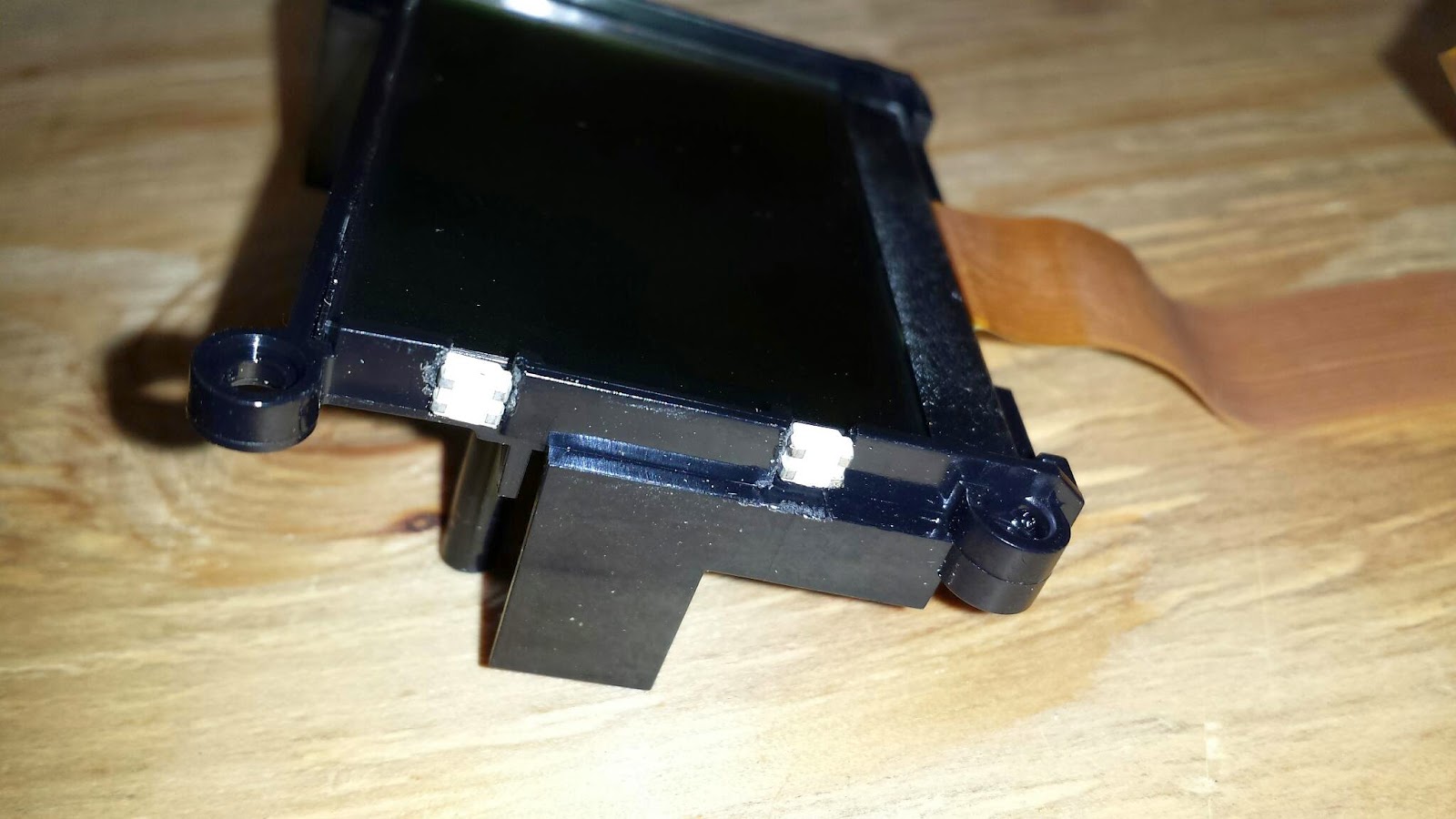
I sat down and ripped the brick apart, got the display out, and started to figure out what I could put where. I was hoping to get an Indeglo backlight and slide it behind the screen. Nope, that was not going to happen this time around. Double-sided adhesive foam is not known for coming apart. Plus I wasn't going to spend that kind of time on it atm. So, I opted to cut some plastic away on the left side of the screen cradle to make just enough room for two tiny surface mount leds I had laying around. This got interesting; as I was constantly in fear of slipping and scratching the lcd or breaking it entirely. I whittled away at the first notch (for what seamed like eternity). I got it done and the fitment of the led just right. I then started on the other one.
Once I got both leds in place, I soldered the wires needed and left about a six inch tail for both leads. I powered them up to ensure all the joints were good. And Vola! I had light. I reassembled the screen into the housing being careful of the wires and the leds (Hot glue would have been good!).
Now, I was on to find a good point to get power from off the EV3. I poured through schematics and probing the board. I tried the programming usb port, but nope. Not enough power there. I found that the full size usb port has a 5v supply, but I can't get to it to solder to it. The main board also doesn't seam to want to budge (More foam tape?). So, I'm going to install a surface mount transistor to automatically turn the LEDs on and off with the main power.
Stay tuned... I'm not finished yet.